One of the most prevalent reasons for mechanical failure is vibration. These vibrations are a result of the unbalance, which causes the machine to shake and eventually collapse. Unbalanced machines may not immediately cause a breakdown, but they might limit the machine’s ability to produce, hence raising production costs due to equipment wear and tear.
Technically speaking unbalance (or imbalance) can be defined as a condition where “a shaft’s geometric centerline and mass centerline” are not coincident, or where “the center of mass is not coincident with the axis of rotation”. In other words, a heavy spot is present somewhere on the shaft or its attachments namely rotors.

What Are the Various Types of Unbalance?
When balancing a rotor, it is significant to understand the various types of unbalance. There are three distinct types of unbalance:
- Static Unbalance; When the mass axis is offset from the shaft axis, an unbalance arises. Only one axial plane could be used to correct static unbalance.
- Couple Unbalance; Couple unbalance occurs when the mass axis intersects with the running axis. This type of unbalance is typically corrected in two axial planes.
- Dynamic Unbalance. Dynamic unbalance is typically a combination of static and couple unbalance and occurs when the mass axis does not intersect with the rotational axis. This can usually be repaired by correcting the balance along two axial planes.
There are many different kinds of conditions that cause an imbalance, such as:
- Uneven accumulation of dust in fan blades.
- Erosion and uneven corrosion of pump impellers.
- Lack of homogeneity in cast parts, such as bubbles, blow holes, and porous parts.
- Rotor eccentricity.
- Unequal distribution in electric motor rotor bars or windings.
- Bent roller, especially in paper industry machines.
- Missing balance weights.
- Bent shaft.
- Eccentricity.
Quantifying unbalance

Imbalance is the most common source of vibration in rotating machinery. It is a very important parameter, and it must be considered carefully in the design of modern machines, especially for machines requiring a high degree of reliability and machines operating at high speeds. Mathematically, the imbalance can be expressed as follows
where
m: unbalanced mass (g);
r: distance of the unbalanced mass from the center axis (mm).
Centrifugal Force due to imbalance can be quantified as below
- The vibration amplitude is directly proportional to the amount of imbalance.
- A variation in imbalance will cause a variation in the vibration phase angle.
- The vector sum of all weights at the same plane is equivalent to a single resulting imbalance.
- The amount of imbalance can be quantified by the weight and distance from the rotor center to the weight (grams x cm). An increase in the imbalance weight or the radius will cause an increase directly proportional to the amount of imbalance where,
m = imbalance mass
d = imbalance radius
w = angular velocity

Unbalance is the most common rotor system malfunction. If neglected can result in the deterioration of the machine’s life. In order to rectify this condition, rotating machines can be balanced. In brief, Balancing is the process of attempting to improve the mass distribution of a body so that it rotates in its bearings without unbalanced centrifugal forces.
Studying Characteristics of Unbalance Machine
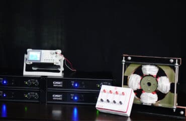
This condition can be simulated in TIERA Machinery Fault Simulator (TMFS). The user can practically experiment with the unbalanced condition in the machine, understand its effects, measure the vibration signature & learn how to balance the machine.


The Simulator has two rotors for studying the static, couple, overhung or dynamic unbalance conditions. The degree of unbalance can be varied using different masses. Sensors like Proximity probes, Velocity sensors, or Accelerometers & Tachometers can be mounted on the kit, for Vibration frequency & phase measurement and to detect the unbalanced condition in the machine.
Measuring the vibration and comparing them with baseline data can help the user to detect the condition of unbalance. Also, measuring the phase data from the drive and non-drive end bearings gives a clear picture of the type of unbalance.


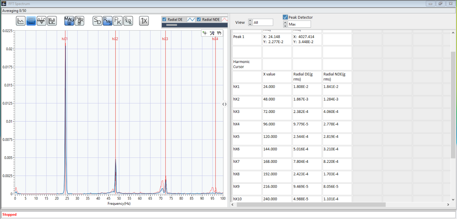
The Accelerometer data was captured using T-DAQ IEPE in T-ViB Time Spectrum Analyzer Software. The graph below shows the spectrum with the vibration frequency data. In the data captured, there is a high amplitude level in the running frequency which is a characteristic of high unbalance. The harmonic cursor used in the graph shows the amplitude levels on the info tab, which helps in the comparison.
The Machine Fault Simulator enables the user
- To simulate real-world machinery problems without the expense of a real machine.
- To learn how to use the sensor, instrumentation, and Software. Collecting good data & understanding the underlying problem requires practice and experience, which can be obtained through experimentation with the simulator, before facing real problems.
- For Software testing and training, for example newly developed Signal Processing techniques of machine fault detection, Machine Learning algorithms, etc.
- For Research and Product Development, for example testing newly developed products like wireless accelerometers, Data Acquisition systems, portable data collectors, etc.